
Bluetooth LED Control with Arduino Uno and HC-05
Bluetooth LED Control with Arduino Uno and HC-05
For this project, I built a simple Bluetooth-controlled LED system using an Arduino Uno and an HC-05 Bluetooth module. The goal was to create a basic wireless command path: send a command from a host device over Bluetooth, receive it on the Arduino through UART, and use that command to control a physical output.
Although the final output was just an LED turning on and off, the real value of the project was in validating and debugging the full communication chain between a wireless module and an embedded system.
Project overview
The system listens for incoming Bluetooth commands and toggles an LED based on the received character:
- sending
'1'turns the LED on - sending
'0'turns the LED off
At a high level, the communication path looks like this:
Host device → Bluetooth link → HC-05 → UART → Arduino → LED output
This project served as a small but useful proof of concept for wireless control and telemetry in embedded systems.
Why I chose the HC-05
I chose the HC-05 because it is one of the most straightforward ways to add Bluetooth communication to a microcontroller project. It communicates through UART, which made it a great learning tool for understanding how serial data moves between devices.
A few reasons I picked it:
- it is inexpensive and widely available
- it is well suited for simple command-and-control applications
- it behaves like a serial bridge, which makes the communication model easier to understand
- it supports AT commands, which made it possible to inspect and configure the module directly
For this project, I wanted to focus on learning the fundamentals of Bluetooth communication before moving on to more advanced telemetry systems.
Hardware used
- Arduino Uno
- HC-05 Bluetooth module
- LED
- current-limiting resistor
- breadboard and jumper wires
- resistor divider for the HC-05 RX path
- host computer for testing and configuration
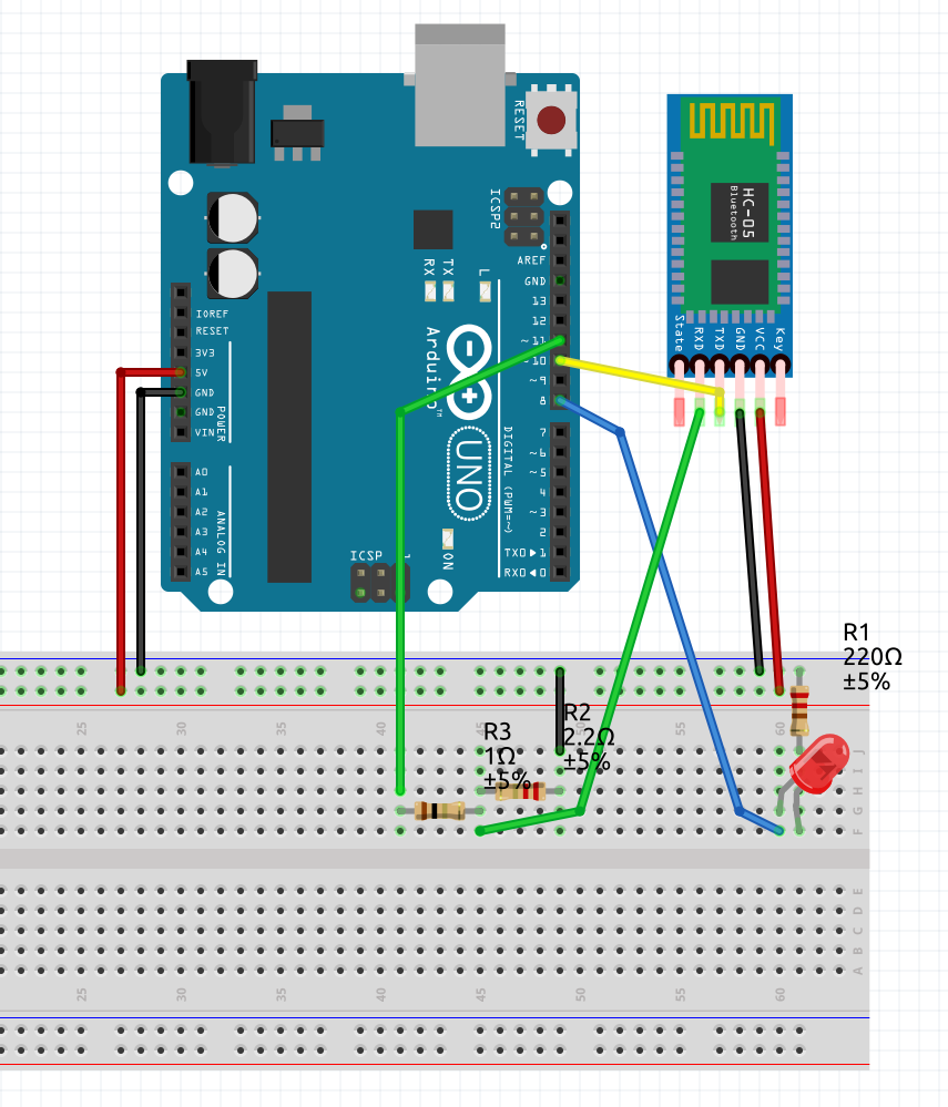
Schematic
Below is the schematic used for the project.
System architecture
At a functional level, the system has three layers:
1. Wireless transport layer
A host device sends a character over Bluetooth to the HC-05.
2. UART interface layer
The HC-05 converts the received Bluetooth data into UART serial data for the Arduino.
3. Application layer
The Arduino firmware reads the incoming character and maps it to a hardware action.
This layering was important because it gave me a structured way to debug the system. If the LED did not respond correctly, the issue could be isolated to one of these layers rather than treated as a single opaque failure.
Software design
The firmware was intentionally kept small so the communication behavior remained easy to inspect. The core logic was:
- initialize serial interfaces
- wait for incoming data from the HC-05
- read one character
- compare the received value against known commands
- update the LED output accordingly
The project also used a separate serial path for debugging so I could inspect command flow without interfering with the Bluetooth test conditions.
Bluetooth LED control code
After validating the HC-05 configuration and serial path, I moved to a simple application-level test: controlling an LED over Bluetooth. The goal of this phase was to confirm that the full communication path was working in normal data mode:
host device → Bluetooth link → HC-05 → Arduino UART parser → LED output
I used the following sketch:
#include <SoftwareSerial.h>

SoftwareSerial BT(10, 11); // RX, TX
const int LED = 8;

void setup() {
  Serial.begin(9600);
  BT.begin(9600);
  pinMode(LED, OUTPUT);
  Serial.println("Bluetooth LED test ready");
}

void loop() {
  if (BT.available()) {
    char c = BT.read();

    Serial.print("Received: ");
    Serial.println(c);

    if (c == '1') {
      digitalWrite(LED, HIGH);
      Serial.println("LED ON");
    }
    else if (c == '0') {
      digitalWrite(LED, LOW);
      Serial.println("LED OFF");
    }
  }
}
What I built
The Arduino listens for Bluetooth input from the HC-05 module. When it receives a valid command, it updates the LED state accordingly. This made it possible to test end-to-end communication from a Bluetooth terminal to a physical output.
The final behavior was simple, but the project covered several important embedded concepts:
- UART communication
- Bluetooth module configuration
- serial debugging
- hardware/software integration
- troubleshooting wiring and interface issues
Key technical concepts
UART communication
The HC-05 communicates with the Arduino over UART, so the project required:
- correct TX/RX wiring
- matching baud rates
- proper serial configuration in software
This was one of the most useful parts of the project because it reinforced how important interface-level details are in embedded systems.
AT mode configuration
Before using the module in normal Bluetooth data mode, I tested it in AT mode. This allowed me to verify that the module was functioning and inspect its configuration.
Using AT commands, I was able to confirm values such as:
- firmware version
- Bluetooth address
- module role
- UART settings
That made the module much easier to trust once I moved into normal operating mode.
SoftwareSerial vs hardware serial
One important lesson was that on the Arduino Uno, pins 0 and 1 are tied to the USB serial interface. Early in the project, this created confusion during testing because I was mixing USB serial behavior with Bluetooth serial behavior.
To isolate the Bluetooth interface more cleanly, I moved the HC-05 to a separate serial path using SoftwareSerial.
Challenges I faced
This ended up being the most valuable part of the project.
1. Serial interface confusion
At one point, I thought the LED was being controlled through Bluetooth, but it was still responding even when Bluetooth was disabled. That made me realize the Arduino’s USB serial interface was affecting the test.
This taught me an important practical lesson: on the Uno, the hardware UART is shared with USB, so serial debugging and Bluetooth testing need to be separated carefully.
2. TX/RX wiring error
One of the biggest issues was that the HC-05 initially did not respond in AT mode. I checked baud rate, AT mode behavior, and Serial Monitor settings before eventually discovering the real issue: the TX and RX lines were reversed.
Once I corrected the wiring, the module immediately started responding.
That was a simple but important reminder that serial communication depends on proper signal crossover:
- device TX goes to other device RX
- device RX goes to other device TX
3. AT mode setup and debugging
Even after getting the module into AT mode, I initially saw no useful response. I had to verify several things step by step:
- that the HC-05 had actually entered AT mode
- that the baud rate was correct
- that the Serial Monitor line ending was set correctly
- that the wiring was correct
Eventually, I confirmed the module settings and successfully queried the device in AT mode.
4. Understanding debugging visibility
Another lesson was realizing that Serial.print() output is only visible when the board is connected to a host reading the USB serial port. That pushed me to think more seriously about how embedded systems can report state when they are running on battery and disconnected from a computer.
This became especially relevant because one of my long-term goals is to use wireless links not only for control, but also for telemetry and debugging.
5. Tooling and environment friction
I also experimented with working across different development environments. Some parts of the Bluetooth setup were more difficult than expected on Ubuntu during early testing, so I temporarily moved to a Windows setup to reduce variables and get the communication path working first.
That experience reminded me that embedded debugging is not only about firmware and hardware. Tooling and host-side environment can also have a major impact on progress.
What I learned
This project taught me much more than how to turn an LED on over Bluetooth.
I learned how to:
- configure and test a UART-based wireless module
- verify serial settings through AT commands
- debug interface-level wiring problems
- separate USB serial behavior from Bluetooth serial behavior
- validate a communication path incrementally instead of changing too many variables at once
Most importantly, I learned that even a simple project can become a meaningful systems-integration exercise when communication, configuration, and debugging are involved.
Why this project matters
Even though the visible result is simple, the real achievement was building and validating a wireless control path between an external device and an embedded system.
That same architecture can be extended into larger projects such as:
- Bluetooth-controlled robot motion
- wireless sensor telemetry
- embedded diagnostics
- mode switching between manual and autonomous behavior
- remote debugging of a battery-powered robot
This project became a useful foundation for the more advanced robotics and telemetry work I want to build next.
Next steps
A few natural next steps for this project are:
- controlling motors over Bluetooth instead of only an LED
- sending diagnostic data back from the robot to the host
- adding manual and autonomous operating modes
- benchmarking the HC-05 against other telemetry options
- comparing the HC-05 on different microcontroller boards
Final thoughts
Although this project started as a simple Bluetooth LED demo, it became a valuable lesson in embedded communication, debugging, and hardware/software integration.
It gave me a practical way to understand how wireless modules interact with a microcontroller at the UART level, and it provided a solid starting point for more advanced robotics and telemetry projects.